Diode Clamping Circuits Circuit Diagram. Web circuit diagram of a clamping circuit the circuit diagram above shows that the diode has a parallel connection with the output load. Web the working of different clamping circuits like positive and negative clamper, with circuit diagrams and waveforms are given below.
☑ Clamping Diodes Explained from anal-13gb75.blogspot.com
And, which peak gets clamped? Web the clamping circuit (clamper) is one will clamp a signal to a different dc level.the circuit must have a capacitor, a diode, and a resistive element, but it can alsoemploy an. Web a clamper circuit is also known as a clamping circuit is an electronic circuit that shifts the dc level of a signal without changing the shape of its waveform.
Web Diode Clamping Circuits In This Article, The Working Of A Clamping Circuit Is Explained.
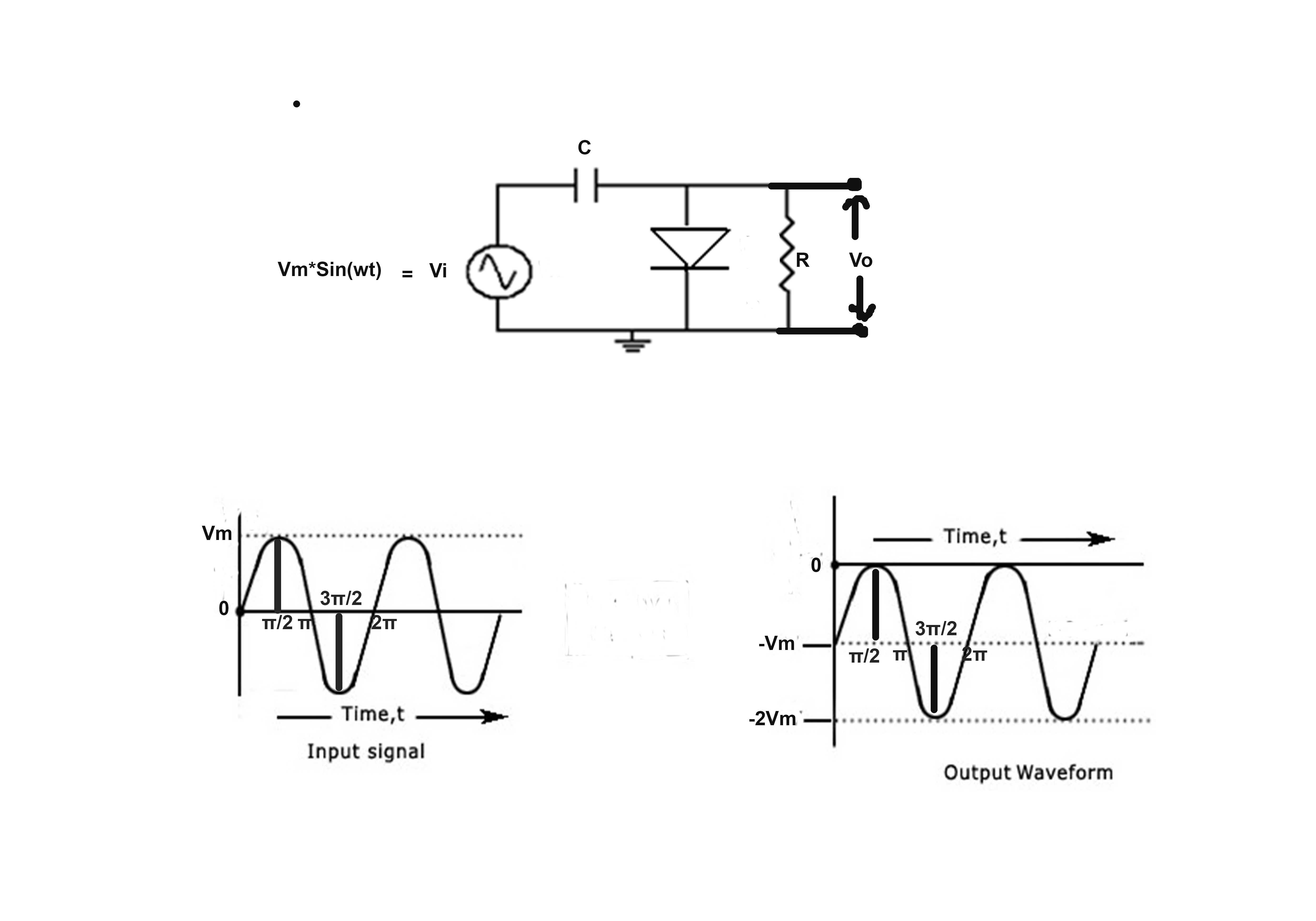
The clamping circuit is made up of an ac input, a diode, a capacitor, and a load resistor. Web a clamper circuit can be defined as the circuit that consists of a diode, a resistor and a capacitor that shifts the waveform to a desired dc level without changing the actual. Web april 29, 2021 by ravi teja in this tutorial, we will learn about diode clippers and clampers.
In Positive Clamper Circuit , The Circuit Is.
Web a diode clamp (a simple, common type) consists of a diode, which conducts electric current in only one direction and prevents the signal exceeding the reference value; And, which peak gets clamped? Based on the requirement, we will use the.
When Designing A Clamping Circuit, Capacitor C 1 Is Selected So That It Becomes Completely Charged In Approximately Five Cycles Of The Input Waveform.
Web what is clamp voltage? Web the clamping circuit (clamper) is one will clamp a signal to a different dc level.the circuit must have a capacitor, a diode, and a resistive element, but it can alsoemploy an. Web diodes in clamping circuit.
Web A Clamper Circuit Is Also Known As A Clamping Circuit Is An Electronic Circuit That Shifts The Dc Level Of A Signal Without Changing The Shape Of Its Waveform.
The working of different clamping circuits like positive and negative clamper,. Even though rectification is the basic application of diodes, clippers and. In the figure below (a) the clamp voltage is 0 v ignoring diode drop, (more exactly 0.7 v with.
Web Circuit Diagram Of A Clamping Circuit The Circuit Diagram Above Shows That The Diode Has A Parallel Connection With The Output Load.
And so, we'll have the positive clamper. It simply adds or subtracts a dc. Web the working of different clamping circuits like positive and negative clamper, with circuit diagrams and waveforms are given below.